
-
Lessons for new concepts
-
Activities for homework
Learn how to get started programming the Linkbot-Arduino combination, by using RoboBlocky's built-in, drag-and-drop LArduino commands to control an LED device!
(See below for hardware and software needed, plus instructions on connecting the LED module to the Arduino, which in turn is connected to the Linkbot.)


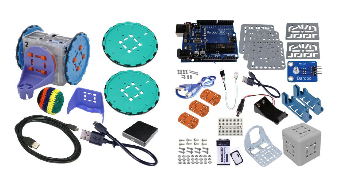
Hardware needed:
Software needed:
RoboBlocky at www.roboblockl.com (free)
To enable control of hardware Linkbots via a computer, download Linkbot Labs for free (or C-STEM Studio including Linkbot Labs)
Connecting the LED module:
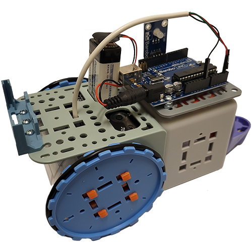
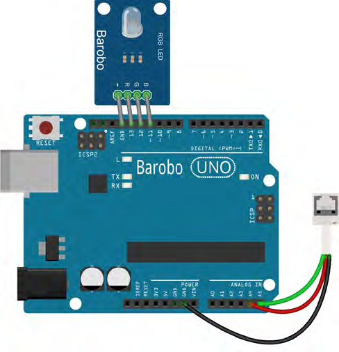
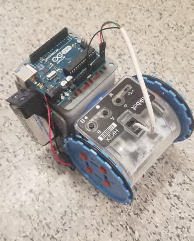
The R, G, and B pins on the LED module plug into digital pins 13, 12, and 11, respectively, on the Arduino, as shown in the first image below. The LED - (ground) pin plugs into the GND pin next to pin 13. The image also shows how the green, red, and black wires from the white cable connector plug into the A5, A4, and GND pins, respectively. The other end of the white cable plugs into the top of the Linkbot (as shown in the second image below, without the LED module installed).
Connecting the Linkbot to the computer (and RoboBlocky):
Instructions on connecting a Linkbot to a computer via RoboBlocky can be found here.